For more information, see Time Slicing Structure in Tutorials.
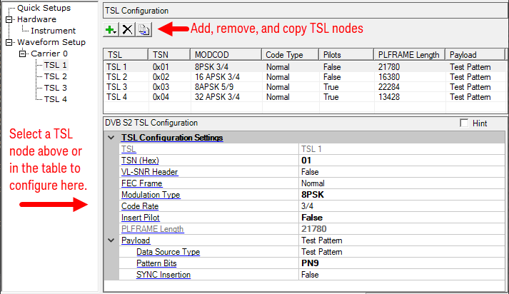
Displays the time slice number
Range: 0x00 to 0xFF
Default: 0x00
Sets or gets the 8-bit sized time slice number in hex for the respective time slice.
Choice: True | False
Default: False
Coupling: FEC Frame, Modulation Type and Code Rate. VL-SNR Header can only be activated in DVB S2X
Double-click or use the drop-down menu to select whether to insert VL-SNR Header in PLFRAME in DVB-S2X.
Choice: Normal | Medium | Short
Default: Normal
Coupling: Modulation Type, Code Rate and Number of LDPC Blocks
Double-click or use the drop-down menu to select whether to use normal, medium or short LDPC block size in DVB-S2/S2X.
FEC encoding performs outer coding (BCH), Inner Coding (LDPC) and Bit interleaving. The input stream is composed of BBFRAMEs and the output stream of FECFRAMEs. Each BBFRAME (Kbch bits) shall be processed by the FEC coding subsystem, to generate a FECFRAME (nldpc bits). The parity check bits (BCHFEC) of the systematic BCH outer code shall be appended after the BBFRAME, and the parity check bits (LDPCFEC) of the inner LDPC encoder shall be appended after the BCHFEC field, as shown below.
![]()
Figure 2 FEC Encoding Data Structure
LDPC encoding provides two kinds of frame length, one is normal frame with length 64800 bit; the other is short frame with length 16200 bit (1/4 of normal frame), shown in the following figure.
Table 1 FECFRAME (normal and short) configurations and application areas
|
System Configuration |
Broadcast Services |
Interactive services |
DSNG |
Professional Services |
|
|---|---|---|---|---|---|
|
FECFRAME(normal) |
64800 (bits) |
N |
N |
N |
N |
|
FECFRAME(short) |
16200 (bits) |
NA |
N |
O |
N |
|
N = normative, O = optional, NA = not applicable. |
|||||
Choice: BPSK | BPSK-S | QPSK | 8PSK | 8APSK | 16 APSK | 32 APSK | 64 APSK | 128 APSK | 256 APSK
Default: QPSK
Coupling: Code Rate
Double-click or use the drop-down menu to select the modulation type.
Gets the LDPC code rate for each physical frame.
Choice: True | false
Default: True
Double-click or use the drop-down menu to select whether to insert pilot at the physical layer in DVB-S2/S2X. For the VL-SNR mode, Insert Pilot is always True.
When Insert Pilot is enabled, a PILOT BLOCK composed of P = 36 pilot symbols will be inserted. Each pilot shall be an un-modulated symbol, identified by I = (1/√2), Q = (1/√2). The first PILOT BLOCK shall be inserted 16 SLOTs after the PLHEADER, the second after 32 SLOTs and so on, as represented in figure 13. If the PILOT BLOCK position coincides with the beginning of the next SOF, then the PILOT BLOCK is not transmitted. Besides, the pilot presence/absence in VCM (Variable Coding and Modulation) and ACM (Adaptive Coding and Modulation) can be changed on a frame-by-frame basis.
Gets the length for each physical layer frame in TSL. This is read-only and calculated by PLS.
The TS payload settings.
Choice: Test Pattern (fixed)
Double-click or use the drop-down menu to select which type to be used as the data source.
Learn more about the different Data Source Types, refer to the page Data Source Type.
The data bits used as test pattern.
Click the right button to open the ![]() Data Pattern Selection dialog and select a test pattern to use.
Data Pattern Selection dialog and select a test pattern to use.
Choice: False (fixed)
Double-click or use the drop-down menu to determine whether a SYNC byte (0x47) should be inserted into the test pattern.